Keywords: Task
Differences between Tasks and Functions
Like functions, tasks can be used to describe common code segments and can be called at any position within a module, making the code more intuitive and readable. Functions are generally used for various conversions and computations in combinational logic, while tasks are more like procedures. They can not only accomplish the functionality of functions, but also include timing control logic. The differences between tasks and functions are summarized below:
| Comparison Point | Function | Task |
|---|---|---|
| Input | A function must have at least one input, and the port declaration cannot contain inout type | A task can have no input or multiple inputs, and the port declaration can be of inout type |
| Output | A function has no output | A task can have no output or multiple outputs |
| Return Value | A function has at least one return value | A task has no return value |
| Simulation Time | A function always starts executing at time zero | A task can execute at non-zero times |
| Sequential Logic | A function cannot contain any timing control logic | A task cannot contain always statements, but can include other timing controls, such as delay statements |
| Call | A function can only call functions, not tasks | A task can call functions and tasks |
| Coding Standards | A function cannot appear as a standalone statement; it can only be placed on the right-hand side of an assignment statement | A task can appear as a standalone statement in a statement block |
Task
Task Declaration
A task is defined at any position in a module and referenced at any position within the module; its scope is also limited to this module.
When a subroutine in a module meets any of the following conditions, a task must be used instead of a function.
- 1) The subroutine contains timing control logic, such as delays, event control, etc.
- 2) There are no input variables
- 3) There is no output or the number of outputs is greater than 1
The Verilog task declaration format is as follows:
task       task_id ;
    port_declaration ;
    procedural_statement ;
endtask
In a task, the keywords input, output, and inout are used to declare ports. input and inout type ports pass variables from outside the task to the inside, while output and inout type ports pass the results back to the outside when the task execution is complete.
When performing the logic design of a task, the port variables declared as input can be regarded as wire type, and the port variables declared as output can be regarded as reg type. However, there is no need to declare the output ports as reg again.
When assigning values to output signals, do not use the keyword assign. To avoid timing confusion, it is recommended to use blocking assignment for output signals.
For example, a task with an XOR function with delay is described as follows:
Example
input [N-1:0] numa;
input [N-1:0] numb;
output [N-1:0] numco ;
//output reg [N-1:0] numco ; //No need to specify reg type again, although specifying it may not be wrong either
#3 numco = numa ^ numb ;
//assign #3 numco = numa ^ numb ; //Do not use assign, because the output is reg by default
endtask
When declaring a task, you can also add parentheses after the task name to enclose the port declarations.
The above design can be changed to:
Example
input [N-1:0] numa,
input [N-1:0] numb,
output [N-1:0] numco ) ;
#3 numco = numa ^ numb ;
endtask
Task Call
A task can appear as a standalone statement in an initial or always block, and the call format is as follows:
task_id(input1, input2, …,outpu1, output2, …);
When calling a task, the ports must correspond in order.
The signals in the module connected to the input ports can be wire type or reg type. The signals in the module connected to the output ports must be reg type; this needs attention.
Call the above XOR function task to complete the buffering of the XOR result.
Example
#(parameter N = 4)
(
input clk ,
input rstn ,
input [N-1:0] a ,
input [N-1:0] b ,
output [N-1:0] co );
reg [N-1:0] co_t ;
always @(*) begin //Task call
xor_oper_iner(a, b, co_t);
end
reg [N-1:0] co_r ;
always @(posedge clk or negedge rstn) begin
if (!rstn) begin
co_r <= 'b0 ;
end
else begin
co_r <= co_t ; //Data buffering
end
end
assign co = co_r ;
/*------------ task -------*/
task xor_oper_iner;
input [N-1:0] numa;
input [N-1:0] numb;
output [N-1:0] numco ;
#3 numco = numa ^ numb ; //Blocking assignment, easy to control timing
endtask
endmodule
Perform a simple simulation of the above XOR function design; the testbench is described as follows.
For the stimulus part, we use a simple task to describe it, making the stimulus look clearer and more concise.
In fact, the most common application scenario for tasks is in testbenches for simulation. Tasks are also not supported for synthesis in some compilers.
Example
module test ;
reg clk, rstn ;
initial begin
rstn = 0 ;
#8 rstn = 1 ;
forever begin
clk = 0 ; # 5;
clk = 1 ; # 5;
end
end
reg [3:0] a, b;
wire [3:0] co ;
initial begin
a = 0 ;
b = 0 ;
sig_input(4'b1111, 4'b1001, a, b);
sig_input(4'b0110, 4'b1001, a, b);
sig_input(4'b1000, 4'b1001, a, b);
end
task sig_input ;
input [3:0] a ;
input [3:0] b ;
output [3:0] ao ;
output [3:0] bo ;
@(posedge clk) ;
ao = a ;
bo = b ;
endtask ; // sig_input
xor_oper u_xor_oper
(
.clk (clk ),
.rstn (rstn ),
.a (a ),
.b (b ),
.co (co ));
initial begin
forever begin
#100;
if ($time >= 1000) $finish ;
end
end
endmodule // test
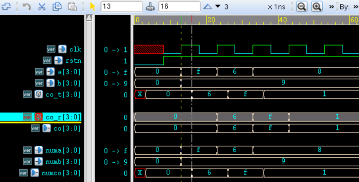
The simulation results are as follows.
It can be seen from the figure that the XOR output logic result is correct, with a 3ns delay relative to the input.
Moreover, the connected signals a, b, co_t remain consistent with the states of the signals numa, numb, numco defined inside the task.
Task Operating on Global Variables
Because a task can be regarded as procedural assignment, the return time of the output port signals is after all statements in the task have been executed.
Variables inside the task are only visible within the task. If you want to specifically observe the operation process on variables in the task, you need to declare the observed variables inside the module but outside the task, which can be called "global variables."
For example, there are the following two descriptions that attempt to use a task to generate a clock.
Example
task clk_rvs_iner ;
output clk_no_rvs ;
# 5 ; clk_no_rvs = 0 ;
# 5 ; clk_no_rvs = 1 ;
endtask
reg clk_test1 ;
always clk_rvs_iner(clk_test1);
//way2: use task to operate global varialbes to generating clk
reg clk_test2 ;
task clk_rvs_global ;
# 5 ; clk_test2 = 0 ;
# 5 ; clk_test2 = 1 ;
endtask // clk_rvs_iner
always clk_rvs_global;
The simulation results are as follows.
In the first description, although the internal variables of the task have process operations of assigning 0 and assigning 1, the intermediate change process is not visible. The final output can only be the final value of the output port signal after all statements in the task are executed. Therefore, the signal clk_test1 is always 1, and this method cannot generate a clock.
In the second description, although there are no port signals, it directly performs procedural operations on the "global variable." Because the global variable is visible to the module, the signal toggling process within the task will be reflected in the signal clk_test2.

Automatic Task
Like functions, the local variables in a task call in Verilog are static. The keyword automatic can be used to declare a task, so that each storage space can be dynamically allocated when the task is called. Each called task independently operates on its own unique address space, without affecting the concurrent execution of multiple calls to the same task.
If a task code segment is called at 2 or more places, it must be declared with the keyword automatic.
When the task is not declared with automatic, and the task is called twice, signal interference may occur, for example, as described by the following code:
Example
input [3:0] cnti ;
input en ;
output [3:0] cnto ;
if (en) cnto = cnti ;
endtask
reg en_cnt ;
reg [3:0] cnt_temp ;
initial begin
en_cnt = 1 ;
cnt_temp = 0 ;
#25 ; en_cnt = 0 ;
end
always #10 cnt_temp = cnt_temp + 1 ;
reg [3:0] cnt1, cnt2 ;
always @(posedge clk) test_flag(2, en_cnt, cnt1); //task(1)
always @(posedge clk) test_flag(cnt_temp, !en_cnt, cnt2);//task(2)
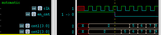
The simulation results are as follows.
When en_cnt is high, the signal en in task (1) is active, and cnt1 can output the correct logic value;
At this time, the signal en in task (2) is not enabled, so the value of cnt2 is overwritten by the shared variable cnt_temp driven by task (1).
When en_cnt is low, the signal en in task (2) is active, so the signal cnt2 in task (2) can output the correct logic value; at this time, under the clock drive, the value of signal cnt1 is repeatedly overwritten by the shared variable cnt_temp driven by task (2).
It can be seen that in the two concurrent calls, the task shares storage space, causing the signals to affect each other.
Other descriptions remain unchanged; only the keyword automatic is added to the above task declaration, as follows.
task automatic test_flag ;
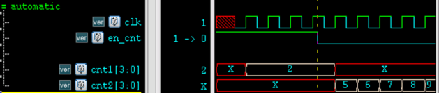
The simulation results at this time are as follows.
- When en_cnt is high, the signal cnt1 in task (1) can output the correct logic value, and the value of signal cnt2 in task (2) is X;
- When en_cnt is low, the signal cnt2 in task (2) can output the correct logic value, and the value of signal cnt1 in task (1) is X;
It can be seen that in the two concurrent calls, because the storage spaces are independent of each other, the signals do not affect each other.
Source Code Download
Download