Keywords: module, port, bidirectional port, PAD
Structural modeling has 3 types of description statements: Gate (gate-level) instantiation statements, UDP (User Defined Primitive) instantiation statements, and module instantiation statements. This section mainly discusses the most widely used module-level instantiation statements.
Module
A module is the definition form of a basic unit in Verilog, and is the interface for interacting with the outside world.
The module format is defined as follows:
module module_name
#(parameter_list)
(port_list) ;
              Declarations_and_Statements ;
endmodule
A module definition must start with the keyword `module` and end with the keyword `endmodule`.
The module name, port signals, port declarations, and optional parameter declarations, etc., appear before the Verilog statements used in the design (Declarations_and_Statements in the figure).
Inside a module, there are 5 optional parts: variable declarations, dataflow statements, behavioral-level statements, low-level module instantiations, and tasks and functions, as shown in the figure below. The order and position of these 5 parts are arbitrary. However, all variables should be declared before use. The specific location of variable declarations is not required, but they must be placed before use.
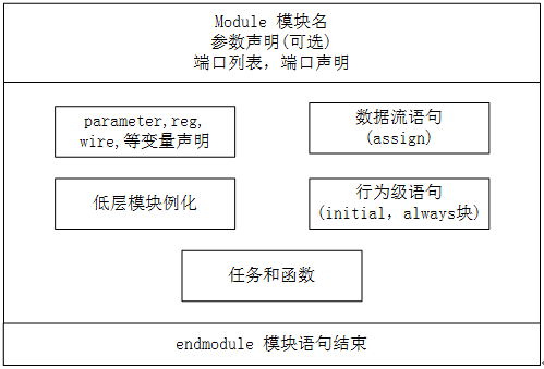
Most of the simulation code earlier uses module declarations; you can refer to it yourself. We will not give specific examples here. When ports are introduced below, we will perform detailed simulations.
Port
A port is the interface for a module to interact with the outside world. For the external environment, the inside of a module is invisible, and calls to the module can only be made through port connections.
Port list
The module definition contains an optional port list, which generally lists signal variables without type and without bit width in the module declaration. Below is a port list for a PAD model:
module pad(
    DIN, OEN, PULL,
    DOUT, PAD);
If a module has no interaction with the external environment, it does not need to declare a port list. For example, in our previous simulations, the test module in the test.sv file did not declare specific ports.
module test ;  //直接分号结束
    ......     //数据流或行为级描述
endmodule
Port declaration
(1) After the port signals are listed in the port list, they can be declared in the module body.
According to the port direction, there are 3 port types: input, output, and bidirectional port (inout).
The input and inout types cannot be declared as reg data type, because the reg type is used to store values, while input ports can only reflect changes in the external signals connected to them, and cannot store the values of these signals.
output can be declared as wire or reg data type.
The port declaration of the pad module in the above example can be expressed in the module body as follows:
Example
input DIN, OEN ;
input [1:0] PULL ; //(00,01-dispull, 11-pullup, 10-pulldown)
inout PAD ; //pad value
output DOUT ; //pad load when pad configured as input
// port data type declaration
wire DIN, OEN ;
wire [1:0] PULL ;
wire PAD ;
reg DOUT ;
(2) In Verilog, ports are implicitly declared as wire type variables. That is, when a port has the wire attribute, there is no need to declare the port type as wire again. However, when a port has the reg attribute, the reg declaration cannot be omitted.
The port declaration in the above example can be simplified as:
Example
input DIN, OEN ;
input [1:0] PULL ;
inout PAD ;
output DOUT ;
reg DOUT ;
(3) Of course, the declaration of signal DOUT can be combined into one statement:
output reg DOUT ;
(4) There is also a more concise and commonly used method to declare ports, that is, to list the ports and their types at the module declaration. Reg-type ports must be declared either in the module declaration or in the module body. For example, the following two writing styles are equivalent.
Example
input DIN, OEN ,
input [1:0] PULL ,
inout PAD ,
output reg DOUT
);
module pad(
input DIN, OEN ,
input [1:0] PULL ,
inout PAD ,
output DOUT
);
reg DOUT ;
inout port simulation
Simulate a pad model that includes the inout port type. The complete code of the pad model is as follows:
Example
//DIN, pad driver when pad configured as output
//OEN, pad direction(1-input, o-output)
input DIN, OEN ,
//pull function (00,01-dispull, 10-pullup, 11-pulldown)
input [1:0] PULL ,
inout PAD ,
//pad load when pad configured as input
output reg DOUT
);
//input:(not effect pad external input logic), output: DIN->PAD
assign PAD = OEN? 'bz : DIN ;
//input:(PAD->DOUT)
always @(*) begin
if (OEN == 1) begin //input
DOUT = PAD ;
end
else begin
DOUT = 'bz ;
end
end
//use tristate gate in Verilog to realize pull up/down function
bufif1 puller(PAD, PULL[0], PULL[1]);
endmodule
The testbench code is as follows:
Example
module test ;
reg DIN, OEN ;
reg [1:0] PULL ;
wire PAD ;
wire DOUT ;
reg PAD_REG ;
assign PAD = OEN ? PAD_REG : 1'bz ; //
initial begin
PAD_REG = 1'bz ; //pad with no dirve at first
OEN = 1'b1 ; //input simulation
#0 ; PULL = 2'b10 ; //pull down
#20 ; PULL = 2'b11 ; //pull up
#20 ; PULL = 2'b00 ; //dispull
#20 ; PAD_REG = 1'b0 ;
#20 ; PAD_REG = 1'b1 ;
#30 ; OEN = 1'b0 ; //output simulation
DIN = 1'bz ;
#15 ; DIN = 1'b0 ;
#15 ; DIN = 1'b1 ;
end
pad u_pad(
.DIN (DIN) ,
.OEN (OEN) ,
.PULL (PULL) ,
.PAD (PAD) ,
.DOUT (DOUT)
);
initial begin
forever begin
#100;
if ($time >= 1000) $finish ;
end
end
endmodule // test
The simulation results are as follows:
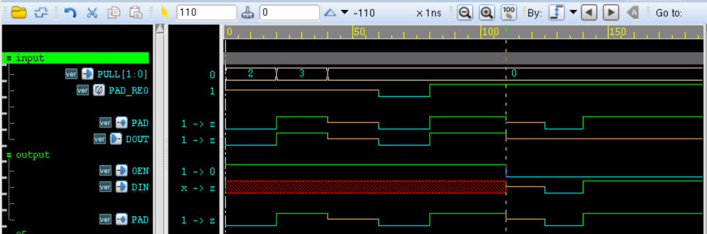
The analysis of the simulation results is as follows:
When the PAD direction is input and there is no driver, the pull function can be reflected through the PAD value.
In the first 60ns, the driving side PAD_REG of PAD is z, which can be considered as no driving. So at the beginning PULL=2, pull-down, PAD value is 0; at 20ns, PULL=3, pull-up, PAD value is 1;
At 40ns, PULL=0, no pull function, and the PAD value input is z.
After 60ns~100ns, the driving side PAD_REG of PAD starts normal driving. At this time, it is equivalent to PAD being directly connected to PAD_REG, so the PAD value remains consistent with its driving value.
In the above analysis, the PAD direction is always input, and all output terminals DOUT remain consistent with the PAD value.
When the PAD direction is output, that is, at 120ns OEN=0, the PAD value remains consistent with the input terminal DIN value.
Source code download
Download