Functional Features
TF (task/function) subroutines are mainly used for data transfer in two directions at the boundary between Verilog and user C programs.
TF subroutines always have the prefix tf_ and are defined in the header file veriuser.h. Therefore, when writing system tasks or functions in C, you need to add #include "veriuser.h" to the C file.
TF subroutines can be divided into the following uses:
- Getting system task information
- Getting parameter list information
- Getting parameter values
- Passing parameter values back to system tasks
- Monitoring changes in parameter values
- Getting simulation time and scheduled event information
- Arithmetic operations
- Displaying information
- Managing and maintaining tasks
- Other tasks such as suspension, termination, saving, and restoration
For a complete list of TF subroutines and their simple usage instructions, refer to the next section."8.3 TF Subroutine List"。
TF Subroutine Examples
The PLI subroutine library has a large number of functions. Explaining them one by one would require a great deal of space. Therefore, it is recommended to study individual subroutines carefully only when needed. Below are examples of some TF subroutines, mainly illustrating the basic flow of designing Verilog system tasks using TF subroutines.
Design Requirements
Sometimes, to reduce the size of the object file after compiling the C language file, or to output debug information in a certain format, the printing function in the software may not use C's built-in printf function, nor the io_printf function from TF subroutines. Instead, it uses the PLI interface and the Verilog system display functions ($display or $write) to implement a user-defined software printing function.
This design implements a software printing function named print_my, with an output format of "string + integer".
Design Analysis
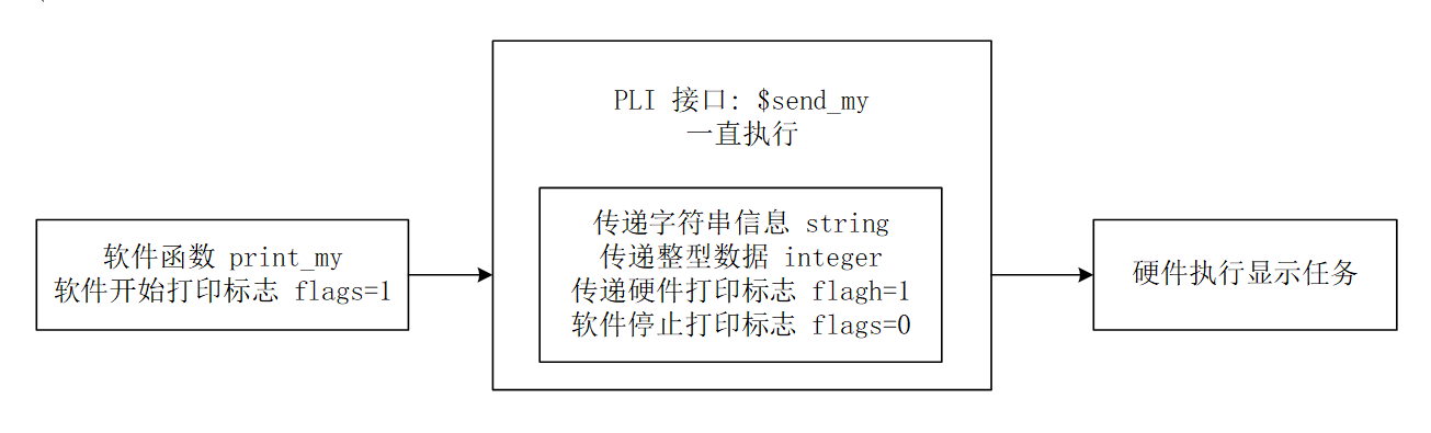
The user-defined software printing function print_my is just an unattractive shell used to pass printing information to software formal parameter variables. To pass the printing information into Verilog, a system task built with TF subroutines is also needed, named $send_my().
It should be noted that system tasks implemented with TF subroutines generally need to be called in Verilog code. The software directly calling this "system task" is equivalent to calling a software function, and has no direct connection with the descriptions of related variables in the Verilog code. Therefore, directly calling the "software function" send_my in the software function print_my is meaningless. It is necessary to add some specific software behaviors in print_my to trigger the system task $send_my to be called by Verilog.
If the digital system contains a CPU, you can use the method of writing to the bus or memory via software, and then monitoring the relevant signal variables in the testbench. This design is relatively small in scale, so another method can be used: Verilog keeps executing the system task $send_my, and a global variable is set in the software function print_my to control whether to perform information transfer and printing.
Software Design
The software design code is as follows, with details explained in the comments. Save it to the file print_gyc.c.
Example
// string to print, integer data, software print start flag
char *str_mes ;
unsigned int int_mes ;
int flags = 0;
//===== define print_my() used in C ======
void print_my(char * str_send, unsigned int int_send){
str_mes = str_send ;
int_mes = int_send ;
flags = 1 ;
}
// character-type data of the ASCII codes corresponding to the string to print, original character length limited to 100
// for example, the character "1" corresponds to ASCII code 0x31, whose character-type data is 0x33, 0x31
char str_mes_format[200] ;
// when TF subroutines pass string-type data, they can only pass data in the relevant base format
// for example, "0xc0de1234" can be passed, but "www.example.com" cannot
// therefore, the original string data needs to be converted into character-type data of the corresponding ASCII codes
void byte2hexstr(char* str, char* dest, int len)
{
char tmp;
int i ;
char stb[16] = { '0', '1', '2', '3', '4', '5', '6', '7', '8', '9', 'A', 'B', 'C', 'D', 'E', 'F' };
for (i = 0; i < len; i++){
tmp = str[i];
dest[i * 2] = stb[tmp >> 4];
dest[i * 2 + 1] = stb[tmp & 15];
}
return;
}
//===== define PLI: send_my() =======
void send_my(){
int i = 0 ;
// detect the software print start flag flags
// and the system task $send_my is called by Verilog with 3 parameters passed in
if (flags && tf_nump()==3) {
// convert the string data to be printed into the string type corresponding to ASCII
byte2hexstr(str_mes, str_mes_format, 100);
// pass the hexadecimal character-type data to the 2nd parameter in the system task send_my
// length is 1600 bits, corresponding to 100 chars and 200 ASCII character-type data
tf_strdelputp(2, 1600, 'H', str_mes_format, 0, 0);
// pass the integer data to the 3rd parameter
tf_putp(3, int_mes);
// pass the hardware print start flag to the 1st parameter
tf_putp(1, 1) ;
flags = 0 ;
}
}
Hardware Design
According to simulation testing, the data passed from software to Verilog is stored in a 1600-bit wide register as shown in the figure below.
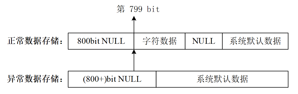
When the register contains normal data, it starts storing normal character data from the 799th bit (half the register width). The remaining low-order bits store "NULL" (corresponding to data 0) and system default data. The lengths of these two parts of data vary according to the length of the normal data stored.
When the register contains no normal data, it uses more than 800 bits of register length to store "NULL" (corresponding to data 0). The remaining width stores system default data.
Based on the above characteristics, normal string data can be detected without printing all the data in the register, avoiding a large amount of blank space in the printed output that would affect appearance.
The hardware Verilog code design is as follows, with specific details explained in the comments. Save it to the file test.v.
Example
module test ;
reg [1599:0] str_my ;
reg [31:0] int_my ;
reg flag_my ;
// continuously check the hardware print flag flagh to determine whether to print
integer i = 1599;
integer j = 1599;
reg [7:0] str_tmp ; // string data storage register
initial begin
flagh = 0 ;
forever begin
#20 ;
// call the system task and pass data from software to hardware (Verilog)
$send_my(flagh, str_my, int_my);
if (flagh) begin // start printing information
#1 ;
// register width has redundancy; printing everything would produce a lot of spaces
// here, unused register bits are detected and suppressed from printing
for(i=1599; i>=0; i= i-8) begin
if (str_my[i -: 8] != 0)
break ;
end
// generally, half the register width is used to store string data
// so when string transfer is correct, data starts from str_my
$display("--DEBUG--- Valid data number: %d", i);
// if there is no string data, str_my will not be completely empty either
// but str_my[799 -: 8] will not have data
if (i<=791) begin
$display("--ERR--- PLEASE INPUT VALID STRING INFO!!!");
$display("--ERR--- Default data number: %d", i);
$display("--ERR--- String data structure: %h", str_my);
end
else begin
$write("---YYY---");
for(j=i; j>=0; j= j-8) begin
str_tmp = str_my[j -: 8] ;
// stop printing when a null character is detected again
if (str_tmp == "") begin
break ;
end
// print character by character
else begin
$write("%s", str_tmp);
end
end
// print integer data
$write("%h \n", int_my);
end
/* $display does not support variable access in register vector part-selects
// so the following description is incorrect; you can only use $write repeatedly to print
else begin
$display("--YYY--- %s%h", str_my[i : j], int_my);
end
*/
flagh = 0 ;
end
end
end
// stop the simulation
initial begin
forever begin
#10000;
if ($time >= 300) $finish ;
end
end
endmodule
Software Invocation
Since the software part of this design cannot execute actively, an additional Verilog system task designed with TF subroutines is added. When this system task is executed in the testbench, it can call the function print_my in the software program.
Add the following C code to the file print_gyc.c:
if (tf_getp(1) == 1) // if the first parameter value of the system function is 1
print_my("It's the first successfull print: ", 0x20170714);
else if (tf_getp(1) == 2) // if the second parameter value of the system function is 2
print_my("2nd: ", 0x09070602);
else
print_my("", 0x1); // if string data is not transferred, report an error
}
Add the following Verilog code to the file test.v:
initial begin
#100 ;
$call_c_print(1);
#100 ;
$call_c_print(2);
#100 ;
$call_c_print(3);
end
Compilation and Simulation
Under Linux, use the following command to compile print_gyc.c and output the print_gyc.o file. Pay attention to relative paths.
gcc -I ${VCS_HOME}/include -c ../tb/print_gyc.cWhen compiling with VCS, you need to create a link table file that VCS can recognize, named pli_gyc.tab, with the following content.
$send_my and $call_c_print are the names of the system tasks called by Verilog;
call=my_monitor, call=call_c_print, etc., indicate calls to functions in the software C program;
$send_my call=send_my
$call_c_print call=call_c_print
Add the following parameter line when compiling with VCS.
-P ../tb/pli_gyc.tab
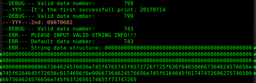
The simulation results are as follows.
As can be seen from the figure, the printed output is normal with no extra blank spaces.
When there is no string data in the printed information, an Error is reported, along with some debug information output.
You can modify some parameters in the testbench to debug and learn about data storage formats.
Chapter Source Code Download
Download