Keywords: synchronous, asynchronous
As known from Chapter 3, when the data at the flip-flop input is unrelated to the flip-flop clock, it is easy to cause the circuit timing to be unsatisfied. This chapter mainly addresses asynchronous problems between modules that can lead to timing violations.
The definitions of asynchronous and synchronous are introduced in many places, with differences in details. The main focus of this chapter is on methods for solving asynchronous problems, not on why asynchronous clocks occur, nor on the specific structure of asynchronous circuits. We only analyze and solve problems from the timing results of asynchronous clocks.
Synchronous clock
In digital design, it is generally considered that two clocks with the same frequency or an integer-multiple frequency ratio, and with the same phase or a fixed phase difference, are synchronous clocks.
Alternatively, it can be understood that two clocks from the same source with an integer-multiple frequency ratio are synchronous clocks. In fact, clocks from the same source guarantee a fixed phase difference. Specifically, they can be classified as follows:
Same source, same frequency, same phase
Such clocks have the same frequency and phase, and are synchronous. Data transmission between clocks only needs to satisfy normal setup time and hold time, without requiring special synchronization design.
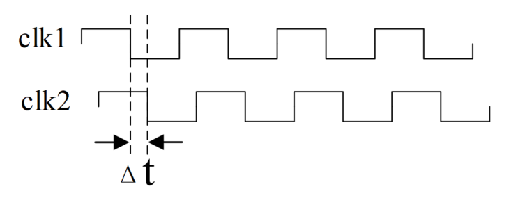
Same source, same frequency, different phase
When two clocks have the same frequency but different phases, they can also be considered synchronous as long as the phase difference remains fixed. Because as long as the data transmission delay between the two clocks is controlled within a reasonable range, timing issues will not occur. Moreover, fixed clock delays can also be repaired in the layout-level netlist.
The fixed phase difference can be understood as the skew between two clocks from the same source due to different paths.
Same source, different frequency but with integer frequency division ratio
In this case, one clock is often a divided version of the other clock, and even if there is a phase difference, it is fixed.
When a single-bit signal is transferred from a slow clock domain to a fast clock domain, because they share the same source, as long as setup time and hold time are satisfied, the fast clock domain will always capture the signal transferred from the slow clock domain.
As shown in the figure below, the rising edge of clk2 can always capture signal sig1 from the clk1 domain, and the high-level duration of the captured signal sig2 is also the frequency ratio of the two clocks, i.e., 2 cycles.
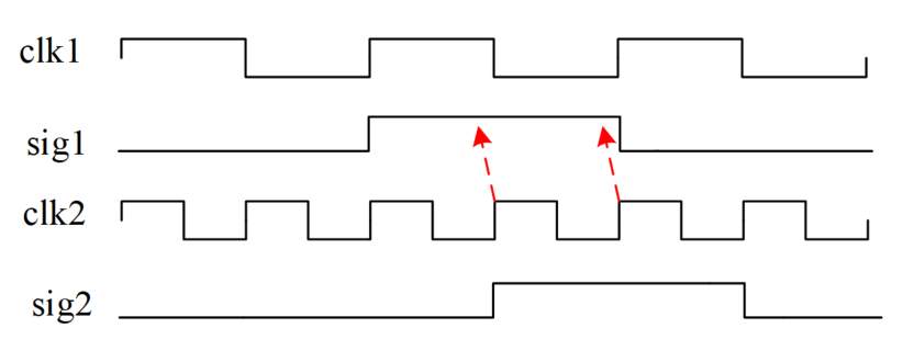
If the signal sig2 in the clk2 domain is required to last only one clock cycle, rising edge detection of sig1 is needed.
Example
reg [1:0] sig2_r ;
always @(posedge clk2 or negedge rstn) begin
if (!rstn) sig2_r <= 2'b0 ;
else sig2_r <= {sig2_r[0], sig1} ;
end
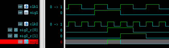
assign sig2 = sig2_r[0] && !sig2_r[1];
The simulation results are shown in the figure below:
When a single-bit signal is transferred from a fast clock domain to a slow clock domain, as long as the slow clock domain can safely capture the signal transferred from the fast clock domain, there is no asynchronous problem, because the two clocks share the same source. See the transmission from sig1 to sig2 in the figure below.
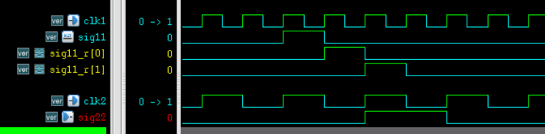
However, if the fast clock domain signal is too narrow, the slow clock domain may miss the signal, as shown in the transmission from sig11 to sig22 in the figure below. In this case, the narrow pulse signal in the fast clock domain needs to be widened.
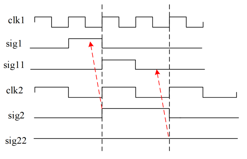
When the frequency ratio of the two clocks is relatively small, the signal can be widened by delaying it in the fast clock domain;
when the frequency ratio of the two clocks differs greatly, a counting method can be used in the fast clock domain to extend the valid time of the single-bit signal.
The Verilog description of the method of widening a narrow pulse signal using delay is as follows. Since the frequency ratio of clk1 to clk2 is 2, it is only necessary to delay by 2 beats in the clk2 clock domain.
Example
always @(posedge clk1 or negedge rstn) begin
if (!rstn) sig11_r <= 2'b0 ;
else sig11_r <= {sig11_r[0], sig11} ;
end
reg sig22_r ;
always @(posedge clk2 or negedge rstn) begin
if (!rstn) sig22_r <= 1'b0 ;
else sig22_r <= |sig11_r ;
end
assign sig22 = sig22_r ;
At this point, the signal in the fast clock domain is delayed by 2 beats and will always be captured by the slow clock domain, as shown in the figure below.
In summary, when the clocks share the same source and the frequency ratio is an integer multiple, the two clocks can be understood as synchronous, and no special synchronization processing is needed. Next, we briefly introduce the case of asynchronous clocks.
Asynchronous clock
When two modules operating under asynchronous clocks exchange data, the uncontrollable clock phase relationship can easily lead to setup time and hold time violations. Clocks in the following 3 cases can be considered asynchronous.
Different source
Two clocks generated by two different clock sources are asynchronous; this is the most common type of asynchronous clock. Even if the two clocks have the same frequency, it cannot be guaranteed that their phases or phase differences are the same after each power-up, so the relationship between signal transmission and the clocks is also uncertain.
Same source but frequency ratio is not an integer multiple
In this case, there may also be multiple phase differences between the two clocks. For example, a 7MHz clock and a 3MHz clock from the same source may also have multiple phase differences between them, making timing difficult to control. In general, they also need to be handled as asynchronous clocks.
Same source, frequency ratio is an integer multiple, but timing requirements are not met
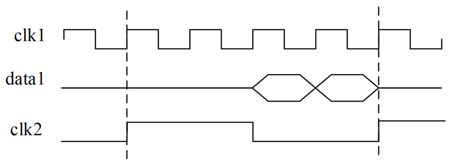
As explained earlier in the discussion of synchronization issues, when a signal is transferred from a fast clock domain to a slow clock domain, there is no asynchronous problem as long as the slow clock domain can safely capture the signal from the fast clock domain. However, if the signal toggles too rapidly in the fast clock domain, the slow clock domain may not safely capture the signal from the fast clock domain, which can also be considered an asynchronous problem.
Generally speaking, timing constraints are relatively relaxed in the slow clock domain, while those in the fast clock domain are relatively strict.
As shown in the figure below, the fast clock domain signal toggles twice before the rising edge of the slow clock domain. At this point, the slow clock domain will miss some data. Moreover, rapid changes in data may also lead to timing violations.
Here we only briefly introduce the classification of asynchronous clocks. Please refer to the following chapters for solutions to asynchronous problems.
Source code download for this chapter
Download