When performing digital design, special situations are often encountered. The tasks and functions in Verilog may no longer meet simulation requirements, and it is necessary to customize some system tasks and functions. The Programming Language Interface (PLI) provides a set of interface routines for accessing the internal data structures of a design and extracting simulation environment information. Users can call these routines to customize system tasks and system functions, and interact with the internal data of the design and the Verilog simulator environment.
PLI Features
In simple terms, Verilog PLI provides a set of C language functions. Designers can call these integrated functions to write software C programs. During RTL compilation, the written software programs are also integrated into the simulation environment. During simulation runtime, by means of system task calls, the data structures in the simulation can be dynamically accessed. This access is bidirectional; not only can information be read from the simulator's data structures, but the information in the data structures can also be modified.
The functionality of PLI is very powerful, and its uses are limited only by the designer's imagination.
- PLI allows users to write custom system tasks and functions in C, and can accomplish complex operations that cannot be done with Verilog.
- Some application software, such as file read/write tools and delay calculation tools, can also be written with PLI.
- PLI can extract design information, such as access hierarchy, interconnection conditions, and the number of specific types of logic elements, etc.
- PLI can be used to write dedicated output display programs, such as some dedicated waveform observers, to generate information such as logic interconnections, hierarchies, and data waveforms.
- PLI can complete tedious monitoring tasks or stimulus tasks.
- PLI can control the simulation process, such as pause and exit, for convenient debugging.
- PLI can also be extended for uses such as RAM/ROM program download tools, power analysis, CModel interfaces, co-simulation environments...
Here is a summary of the frequently used features of PLI:
- (1) Implement co-simulation of CModel and Verilog models. For relatively complex systems, developers often need to first create a working model described in the C language, and then rewrite it module by module into Verilog descriptions.
- (2) Generate test stimuli, or directly perform verification. For input stimuli with a relatively large amount of data, relatively complex control inputs, and data verification in specific environments, PLI implementation has more advantages than Verilog.
- (3) Capture the simulation process and results, and output them in a way that is easy for users to accept. For example, for some encoding/decoding modules, using user-defined display effects makes debugging easier.
- (4) Software-hardware co-simulation. For example, if the design contains a CPU entity, the software can be compiled into machine code and loaded into the corresponding ROM for co-simulation.
PLI Versions
The development of PLI has mainly gone through 3 generations.
1985 - TF Interface
The first generation is called the Task/Function interface, referred to as the TF interface. The TF interface contains a set of C function libraries, all prefixed with tf_, defined in veriuser.h. These C functions are generally called TF routines, mainly including user-defined tasks and functions, utility functions, callback mechanisms, and data write output.
1989 - ACC Interface
The second generation is called the Access interface, referred to as the ACC interface. The functions in the ACC interface are all prefixed with acc_, defined in acc_user.h. ACC routines are mainly used to access and modify various objects described in Verilog. The ACC library functions are an overlay of the TF library functions, not a replacement.
Generally, the PLI interface specifically refers to the TF and ACC interfaces.
1995 - VPI Interface
The third generation is called the Verilog Process Interface, referred to as the VPI interface. VPI routines are a collection of the functions of TF and ACC routines, defined in vpi_user.h.
Compared with the numerous and messy PLI routines, VPI appears particularly refined. Since PLI had no unified standard at its birth and developed entirely through practice, there are nearly a hundred commonly used PLI library functions, and writing programs basically requires consulting the manual.
VPI, on the other hand, is formulated through overall planning according to certain standards, incorporating many object-oriented ideas, and its library functions are far more streamlined than PLI. However, VPI has a relatively complex structure and is not easy to get started with. The biggest weakness of VPI is still that its support for simulators is not friendly.
2003 - SystemVerilog and DPI
As an extension of Verilog, the SystemVerilog standard was released in 2003, supporting more forms of simulation.
The DPI interface (Direct Procee Interface) has become the interface for interaction between software and SystemVerilog, and is currently the mainstream.
In general, using the TF and ACC interfaces of PLI is sufficient to meet simulation requirements. This chapter only provides a brief introduction to the TF and ACC interfaces. As for the other interfaces, they will be shared with everyone one by one when that young person completes their studies.
PLI Usage
By writing system tasks and system functions, users can extend the Verilog language with PLI and C programs. The names of these user-defined system tasks and functions must begin with the dollar sign "$". At this time, a task in Verilog is equivalent to a subroutine. When a task is called, the simulator's execution flow jumps to the subroutine, and after the task is completed, the execution flow returns. Verilog tasks do not return values, but they can have input, output, and bidirectional formal parameters.
Functions in Verilog are the same as functions in most languages. When a function is called, it runs a set of instructions and then returns a value to the instruction that called it.
PLI Flow
The basic flow for using the PLI interface to complete user-defined system tasks is shown below.
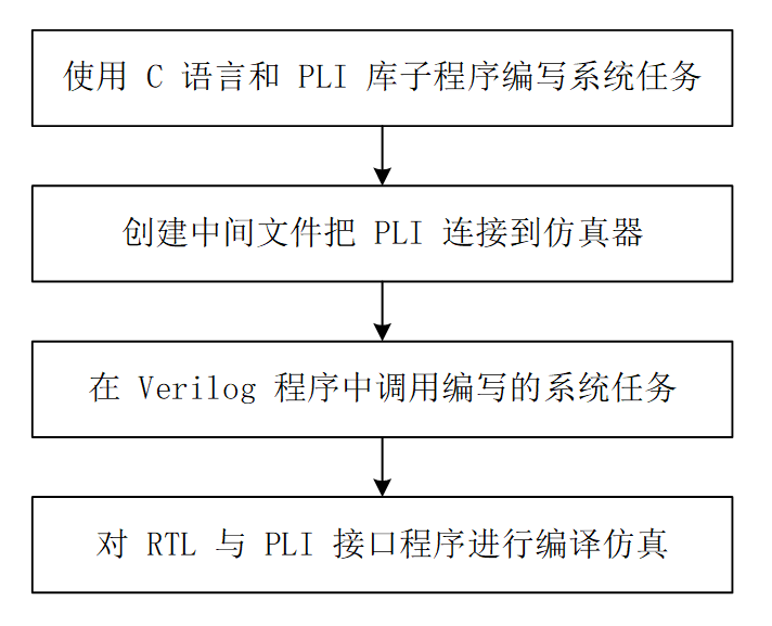
The following uses the simple system task $hello_example as an example for explanation. When this system task is called, it outputs a line of string "Hello Example!".
Writing System Tasks with PLI
The printing program described in C language is shown below, and the file is namedhello_example.c 。
To illustrate the general flow of PLI usage, this program does not call TF/ACC routines.
Example
int hello_example(){
printf("Hello Example! \n");
}
Connecting PLI to the Simulator
Taking VCS usage as an example, compile or create the C-related files needed during VCS compilation.
Perform a simple compilation of the above hello_example.c and output the hello_example.o file. Pay attention to the relative path.
gcc -c ../tb/hello_example.c
Create a link table file recognizable by VCS, named hello_example.tab, with the content as follows.
$hello_example call=hello_example
Calling System Tasks in Verilog
In Verilog, call $hello_example in the form of a system task call, described as follows.
Example
module test ;
initial begin
#10 ;
$hello_example;
end
initial begin
forever begin
#100;
if ($time >= 10000) $finish ;
end
end
endmodule
Verilog Compilation and Simulation
Compile the RTL and the written PLI intermediate files. When indicating that the table file in the PLI library needs to be linked, the "-P" parameter should be used to specify it. For example, in this simulation, the following parameter should be added to the VCS command line (pay attention to the relative path):
-P ../tb/hello_example.tab hello_example.o
The printed information can be seen in the simulation results, as shown in the screenshot below.

Source code download for this chapter
Download