Functional Features
The main functions accomplished by ACC subroutines are:
- Reading information about specific objects from internal data structures
- Writing information about specific objects into internal data structures
The object types that ACC subroutines can operate on are:
- Module instances, module ports, module end-to-end paths, and paths between modules
- Top-level modules
- Primitive instances and primitive ports
- Variable types such as wire, reg, parameter, integer, time, real, etc.
- Timing checks
- Named events
The main characteristics of ACC subroutines are:
- All are prefixed with acc_
- At the beginning, acc_initialize() must be called to initialize the environment
- At exit, acc_close() must be called
- When using functions from the ACC library, the header file acc_user.h must be included
- The concept of handles is used to access objects. A handle is a predefined data type pointing to a specific object in the design. Once a handle is obtained, all information about the object can be accessed. This is similar to the file handle concept in C language. Handles are declared with the keyword handle.
The main types of ACC subroutines are:
- Handle subroutines (handle): return a handle to an object in the design, always prefixed with acc_handle_.
- Next subroutines (next): return a handle to the next object in a specific set of objects in the design, always prefixed with acc_next_, and take the referenced object as a parameter.
- Value Change Link (VCL) subroutines: can add and remove objects from the list of objects monitored for value changes, always prefixed with acc_vcl_, and have no return value.
- Fetch subroutines (fetch): can extract attribute information such as hierarchical paths, always prefixed with acc_fetch_.
- Miscellaneous subroutines (miscellaneous): used to perform various miscellaneous operations related to access subroutines. For example, acc_initialize() and acc_close() are both miscellaneous subroutines.
- Modify subroutines (modify): can modify internal data structures.
For the complete list of ACC subroutines and their brief usage instructions, refer to the next section"8.5 ACC Subroutine List"。
ACC Subroutine Examples
Below are usage examples for only some ACC subroutines, mainly illustrating the basic process of designing Verilog system tasks using ACC subroutines.
Design Requirements
This time, design a system task that monitors a counter.
On one hand, the system task monitors the value of a counter in Verilog; on the other hand, after detecting the counting clock in Verilog, it also performs software counting and compares the software and hardware count values to verify the correctness of the hardware logic. At the same time, when the counter counts to a specific value, it outputs the values of some signal variables.
This design approach is also a common scenario for PLI interfaces. Software implements a logic function, called CModel. Then hardware also implements the same logic function using Verilog. Through the PLI interface program, the software and hardware programs can execute simultaneously and compare results to verify the correctness of the hardware logic design.
Design Analysis
In the PLI interface part, a Value Change Link subroutine is used to monitor the clock. As soon as a rising edge of the clock arrives, a software function is called to perform software counting and compare the software and hardware count values.
Software Design
The software design code is as follows, with details explained in the comments. Save it to the file monitor_gyc.c.
Example
handle hand_rstn, hand_clk, hand_cnt, hand_cout ;
int cnt_soft = 0 ; //Value of the software counter
int cout_soft = 0 ; //Overflow bit of the software counter
//Software counting and comparison function
void act_monitor(){
p_acc_value value ; //Declare the structure variable defined in ACC
//Read the value of a signal variable in Verilog, string type
char *rstn_rtl_str = acc_fetch_value(hand_rstn, "%d", value);
char *clk_rtl_str = acc_fetch_value(hand_clk, "%d", value);
char *cnt_rtl_str = acc_fetch_value(hand_cnt, "%d", value);
char *cout_rtl_str = acc_fetch_value(hand_cout, "%d", value);
//Convert string to integer
int rstn_rtl = atoi(rstn_rtl_str) ;
int clk_rtl = atoi(clk_rtl_str) ;
int cnt_rtl = atoi(cnt_rtl_str) ;
int cout_rtl = atoi(cout_rtl_str) ;
//Software counter
//Reset
if (!rstn_rtl) {
cnt_soft = 0 ;
cout_soft = 0 ;
io_printf("---iii--- Reset state! \n");
}
//Normal operation
else if (rstn_rtl && clk_rtl) {
if (cnt_soft == 9) {
cnt_soft = 0 ; //Count 10
}
else {
cnt_soft = cnt_soft + 1 ; //Count
}
}
cout_soft = cnt_soft == 9 ? 1 : 0 ; //Carry
//Compare software and hardware counts when the clock is low; this is a relatively safe time
if (!clk_rtl && rstn_rtl) {
if ((cnt_soft != cnt_rtl) || (cout_soft != cout_rtl)) {
io_printf("--Err--- rtl cnt: %d, and soft cnt: %d\n", cnt_rtl, cnt_soft);
io_printf("--Err--- rtl cout: %d, and soft cout: %d\n", cout_rtl, cout_soft);
}
//If there is no error in the software and hardware count comparison, output the state values of the signals when one counting cycle is completed
else if (cnt_soft == 9) {
io_printf("--Monitor--- rtl and soft cnt: %d\n", cnt_soft);
io_printf("--Monitor--- rtl and soft cout: %d\n", cout_soft);
}
}
}
//PLI interface, monitoring clock changes
void my_monitor() {
acc_initialize(); //Initialization is required
//Get the handle variable of the first parameter of the system task my_monitor
hand_rstn = acc_handle_tfarg(1);
hand_clk = acc_handle_tfarg(2);
hand_cnt = acc_handle_tfarg(3);
hand_cout = acc_handle_tfarg(4);
//"#define VCL_VERILOG_LOGIC 2" in acc_user.h
//Indicates the VCL callback mechanism shall report
//Once hand_clk changes, call the act_monitor function
acc_vcl_add(hand_clk, act_monitor, null, vcl_verilog_logic);
acc_close(); //Close the task
}
Hardware Design
The Verilog description of a decimal counter is as follows. Save it to the file counter10.v.
Example
input rstn,
input clk,
output [3:0] cnt,
output cout);
reg [3:0] cnt_temp ;
always@(posedge clk or negedge rstn) begin
if (! rstn) begin
cnt_temp <= 4'b0 ;
end
else if (cnt_temp==4'd9) begin
cnt_temp <=4'b000;
end
else begin
cnt_temp <= cnt_temp + 1'b1 ;
end
end
assign cout = (cnt_temp==4'd9) ;
assign cnt = cnt_temp ;
endmodule
testbench
The testbench description is as follows. Save it to the file test.v.
Example
module test ;
reg rstn, clk ;
wire [3:0] cnt ;
wire cout ;
initial begin
rstn = 0 ;
clk = 0 ;
#19.8;
rstn = 1 ;
end
always #5 clk = ~clk ;
counter10 u_cnt(
.rstn (rstn),
.clk (clk),
.cnt (cnt),
.cout (cout));
initial begin
$my_monitor(test.rstn, test.clk, test.cnt, test.cout);
end
initial begin
forever begin
#100;
if ($time >= 300) $finish ;
end
end
endmodule
Compile and Simulation
Under Linux, use the following command to compile monitor_gyc.c and output the monitor_gyc.o file. Pay attention to the relative path.
gcc -I ${VCS_HOME}/include -c ../tb/monitor_gyc.cWhen compiling with VCS, you need to create a link file that VCS can recognize. Name the file pli_gyc.tab, with the following content.
$my_monitor is the name of the system task called in Verilog;
call=my_monitor means calling the function my_monitor() in the software C program;
acc=rw:* sets the attributes of the system task. rw indicates that internal data can be read and written. After the colon, the module or signal region that the system task acts on can be declared. ":*" means it can act on all modules.
$my_monitor call=my_monitor acc=rw:*
Add the following parameter line when compiling with VCS.
-P ../tb/pli_gyc.tab
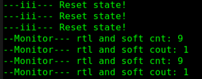
The simulation result log is as follows.
From the log, it can be seen that the software and hardware count comparison is correct, and the status after the counter completes one cycle of counting is also normal.
Chapter Source Code Download
Download